Reconstruction and Visualization of 3D Freehand Ultrasound
Director:       Nassir Navab
Supervisor:     Wolfgang Wein
Student:        Fabian Pache
3D freehand ultrasound scans consist of a large number of position-encoded 2D slice images from the respective anatomy. One means to visualize them is to directly display the stack of slices using certain blending techniques e.g. with OpenGL??. On the other hand the data can be reconstructed into a volume with regular spacing, which in turn can be presented using Volume Rendering techniques. This so-called spatial compounding can be done using a variety of different approaches, some of which can improve the image quality or even eliminate deformation and errors in the original image data. In this Diplomarbeit, different existing and novel compounding methods are to be implemented and evaluated. In addition, other representations for better three-dimensional display of such data will be examined, especially with respect to a fused visualization involving Computed Tomography (CT) data of the same anatomy.
Parameterspace
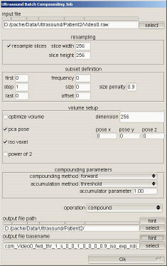
The parameters for compounding have become quite numerous as can be seen on the screenshot of the batch compounding UI. This UI controls a majority of the parameters governing volume creation.
Some of the parameters are described below.
Volume layout
The volume is always choosen to contain the entire sequence to be compounded. The excact layout of the volume depends on
- Volume dimensions can either be explizitly choosen or optimized to reduce the number of unused voxel
- The pose of the volume. The volume is always a cuboid but it is not neccessarily axis aligned. Other alignments are user defined, to ease integration with CT-scans or pca aligned to maximize voxel usage
- The shape of individual voxel. Isotropic voxel are far more placable concerning volumetric algorithms and visualization. When combining isotropic voxel and explizit volume dimensions usually a far greater volume than required is described.
forward vs. backward compounding
Forward compounding inserts each slice into the volume, one pixel at a time. To account for voxels having a thickness that individual slices lack, a slice is inserted multiple times.
Forward compounding: For each pixel find its location inside the volume
One advantage of forward compounding is the possibility to create realtime compounding solutions which are quite commonly covered in literature
In contrast backward componding traverses all voxels, determining the slices and their respective pixel that define the voxel.
Backward compounding: For each voxel find the defining pixel
. This approach cannot be used to incrementally build volumes as the slices become available. But this is also the only drawback. Backward compounding has prooved itself to be more robust, creating volumes of higher quality. Optimizations that exploit the layout of the volume permit this method to run at competitive speeds.
|
 |
Compounding quality enhancements
intuitive error metric
The first step towards a better visualization of volumetric ultrasound is the creation of better ultrasound volumes. Since it is not always obvious when a particular volume is better than another, I definend the metric for volume quality as
The smaller the difference between an original slice and projected slices extracted at the position and orientation the original slice was inserted, the greater the image quality
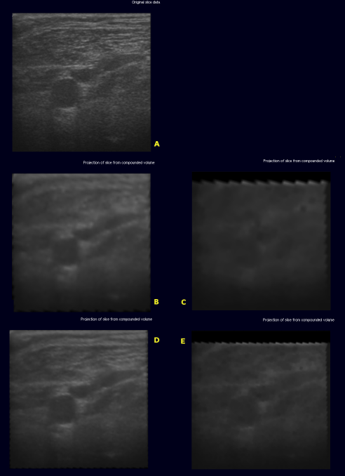
Introducing the original slice as reference produces qualitfiable comparisons between volumes. When comparing forward and backward compounding the results are obvious enough that no numerical evaluation of the error metric is neccesary.
The image below shows the original slice (A) extracted from
- (B) - volume with edge length 128 using backward compounding
- (C) - volume with edge length 128 using forward compounding
- (D) - volume with edge length 256 using backward compounding
- (E) - volume with edge length 256 using forward compounding
This very intutive metric can not be used for calibration, however. Calibration determines the spacial relationship between the tracker node and the recorded images. Reduction of image quality during compounding occurs due to different slices not agreeing on the value of a single voxel. One way to minimize those disagreements would be spread the slices apart until each voxel is determined by zero or one pixel. This obviously can not be our aim. To stop a linear optimizer from seperating the slices to minimize the error, the error measure is taken at locations where no slice was inserted
|
 |
Error metric enhancements for calibration
For the error metric to be usable for calibration it has to be refined. Otherwise the optimzer would be encouraged to procude wrong results.
To calculate the compounding error of a set of N slices, create the volume with slices odd numbered slices and extract virtual slices at the position of even slices. Minizing the compounding error by manipulation of calibration parameters maximizes volume quality
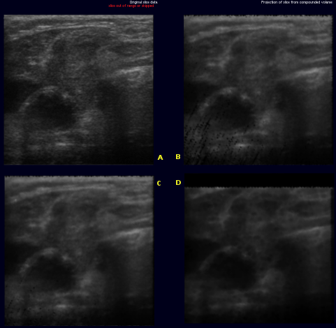
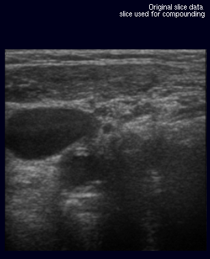
The images on the right illustrate this new metric. The original slice (A) was not used for the creation of the volume. Slices (B) through (D) are virtual slices extracted at the location (A) would have been inserted, each from a volume created with different parameters. In an ideal world, all three extacted slices would be equal to the original slice.
- (B) was extracted from a volume created with backward compounding using only every 4th frame, ie. only frames with index modulo 4 equal 0 were used. the slice was extracted in the middle of a gap, i.e where index modulo 4 equals 2. The black dots in lower left quadrant are artifacts where extrapolation would have been used insted of accumulation.
- (C) was extracted at almost the same location, only from a volume where every second frame was skipped. Artifact occur as described above
- (D) differs from B only in that forward compounding was used instead of backward
Comparing (B) and (D) shows that, artifacts aside, more detail is retained in backward compounding. Comparing (B) and (C) shows that backward compounding quality is largely invariant to the spacing as long as it remains dense enough. Artifacts occur once the spacing exceeds a certain margin. Removal of said artifacts is current research topic
|
 |
Accumulator parameters
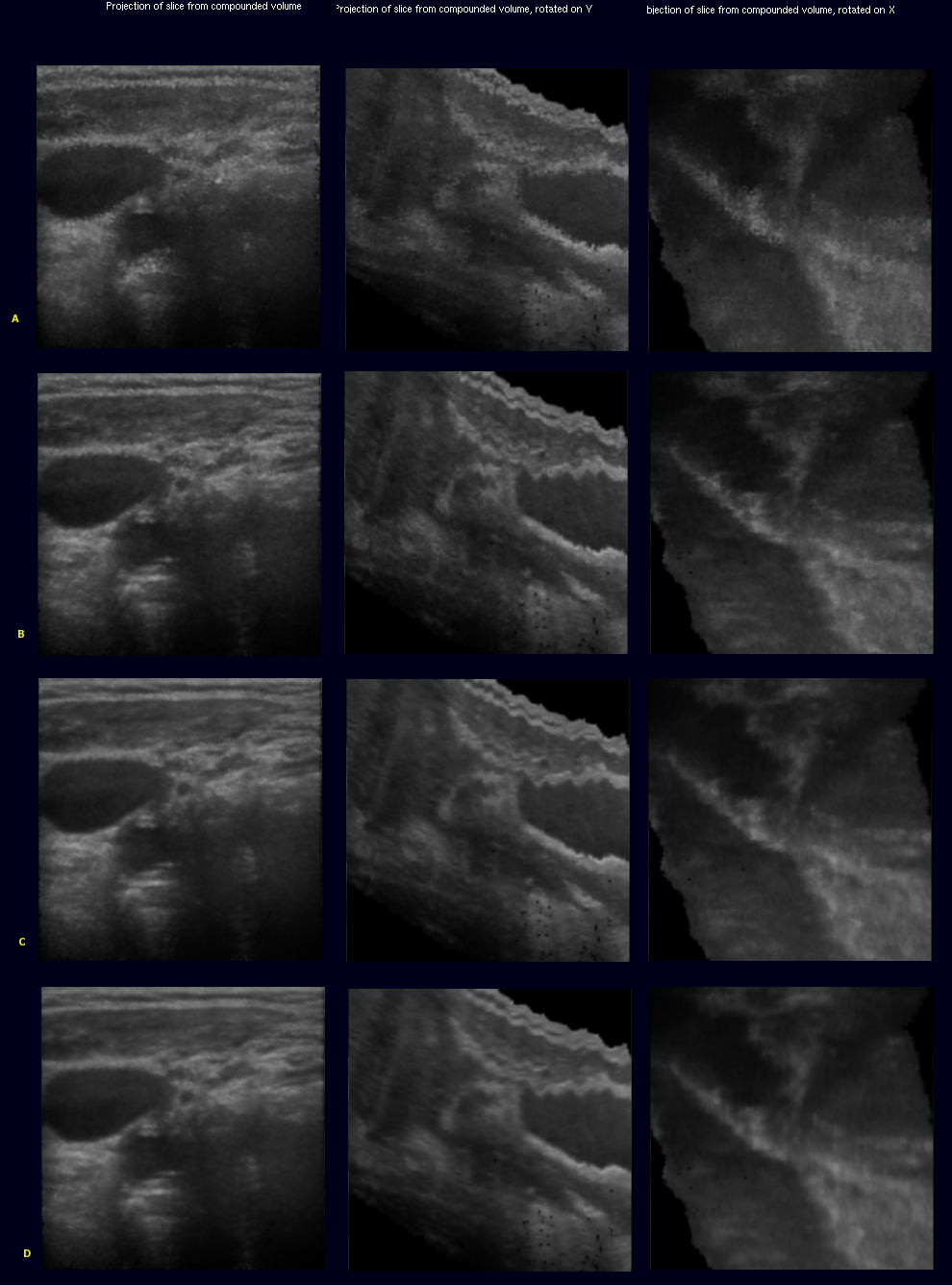
The backward compounding method has been extended so that different methods of accumulation and volume generation can be easily tested. The Accumulator gathers all intensity values with their according weights that define a single voxel. once all potential information has been entered the Accumulator is queried for its final value. The accumulator methods presented here are
- Gaussian smoothing - All values entered (that are closer than a certain threshold) are weighted. The returned value usually is not one that was explicitly entered. The images resulting from gaussian accumulation are less detailed but have a very smooth appearance
- Weighted Selection - Basic Selection, with its most prominent the median, do not allow for different weights except by multiple insertions of the same value. The weighted Selection used here permits a real-valued weights. The returned value is one that was found in the original slices.
- Threshold - Only the closest value being inserted is returned, as long as the value is close enough
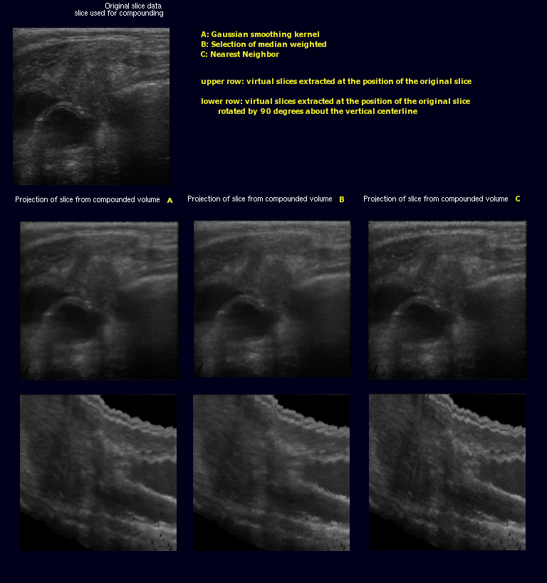
Accumulator selection
Left column originally shown on the right side. second column rotated by 90 deg by y centerline. third column rotated by 90 deg about x centerline
- (A) voting, bugged please ignore
- (B) threshold
- (C) weighted selection
- (D) gauss
|
 |
