SEP
3D view of stereo laparoscope in the operating room
| SEP by: | Benjamin Stetter |
| Advisor: | Prof. Dr. Nassir Navab |
| Supervision by: | Joerg Traub |
Introduction
In minimally invasive surgery, instruments and an endoscope camera are inserted
into the patient's body through small ports or incisions, respectively. In
contrast to conventional methods, operative blood loss as well as
post-operative pain is minimized and recovery times are reduced. However, the
difficult handling of instruments (hand-eye coordination), the lacking tactile
perception, the limited working area, and a restricted vision can often cause
problems. Some of these problems are caused by the currently used visualization
technique of the endoscope images in the surgery room. The acquired images are
shown on an ordinary two-dimensional monitor. Therefore, the surgeon's spatial
perception is missing the depth information. Currently, this loss is mainly
compensated by haptic feedback which is often unsatisfactory for a surgeon.
Although stereoscopic cameras are available, an adequate display of
three-dimensional video is not yet realized mostly due to the lack of ergonomic
visualization techniques. Indeed novel 3D monitors provide up to eight
different views and hence allow a stereoscopic video within a wide range of
sight, even if spectators observe the screen from different perspective angles.
This is ideal in a common operating environment. The acquired stereo images
need to be properly displayed on the 3D monitor. Therefore, an image frame and
its corresponding depth map needs to be provided to the monitor.
A current Diploma thesis by
Hauke Heibel addresses on the problem. The goal of the thesis is to
take the information a stereoscopic endoscope provides and calculate a depth
map of the scene.
Short project description
The objective of this SEP is to embed Haukes work in a system with stereoscopic
cameras and a 3D monitor. The cameras and the monitor are both provided by
Armin Schneider who works at "Klinikum Rechts der Isar - MITI".
In the course of this SEP two main things have to be done:
-
Camera calibration
Initially, the stereoscope is calibrated to determine the fundamental matrix, providing the relation between corresponding points in the stereo images, as well as intrinsic and extrinsic parameters of each camera. We assume that the spatial relation between the two endoscope cameras is rigid. Thus we have to perform the calibration procedure only once. Only if zooming function is used, we need to have an additional calibration step for recovering the variable intrinsic parameters.
-
Visualisation on the 3D monitor
The depth maps along with reference images have to be provided to the monitor, whose software computes the eight necessary images for the 3D view.
For a detailed description of the project have a look at the Kick-Off Presentation or read the two following sections about camera calibration and the visualisation on the 3D monitor.
Camera calibration
The calibration of the cameras can be divided into the computation of the camera matrices and the determination of the fundamental matrix. Both steps are described below.
1. Computation of camera matrices
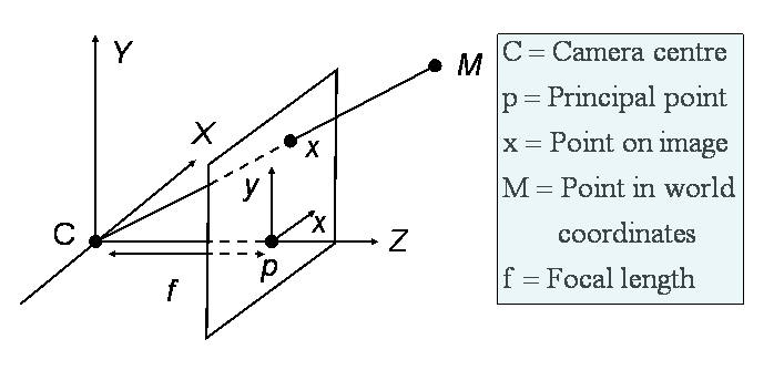
To get you familiar with cameras this section starts with the description of a simple camera model. The "pinhole camera" projects points of the 3D world to points of a 2D image plane. In the picture below a point M in space is mapped to the point on the image plane where the line joining M to the camera centre C meets the image plane.

A camera matrix P is a 3x4 matrix that describes the mapping of homogeneous 3D world to 2D image points. To get the image point x of a world point M, M has to be multiplied from the right to the camera matrix P. This is written as:
x = PM
The camera matrix P contains two groups of parameters, namely intrinsic- and extrinsic parameters. Both groups of parameters can be treated separately and the matrix P can be split into a matrix K, containing the intrinsic parameters and a matrix E, containing the extrinsic parameters. Afterwards P can be computed by a multiplication of E and K: P = E*K
The intrinsic camera matrix is a 3x3 matrix containing the following parameters:

As you can see in the picture above the focal length f is the distance between
the camera center and the principal point. mx and my are
scale factors for the ratio of the pixels of the camera which is also known as
the camera's aspect ratio. The parameters px and py determine
a translation which translates the principal point to the origin of coordinates
in the image plane. s is a skew parameter which is 0 if the x- and y axis of
the camera are perpendicular. If s is greater or less than 0 it shears the
cameras coordinate system to a perpendicular coordinate system.
The extrinsic camera matrix is a 3x4 matrix containing the following parameters:

R is an ordinary rotation matrix that rotates the world coordinate system to the camera coordinate system. The parameter RD is a two element vector which translates points from world coordinates to the camera coordinate system.
To sum up: The matrix K contains all the internal parameters of the camera and the matrix E fits the world coordinate system and the camera coordinate system by a rotation and a translataion.
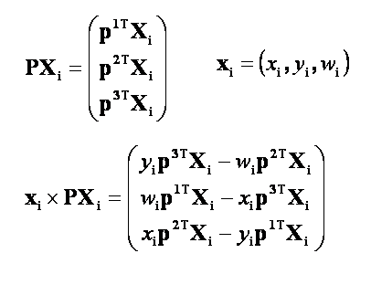
The camera matrix P can be computed by six point correspondences xi <-> Miwhich lead to the six equation systems xi= PMi . An appliance of the cross product operation with PMiform the right side transforms the equation systems to xi x PMi = 0. The left side of the equations can be written down as:

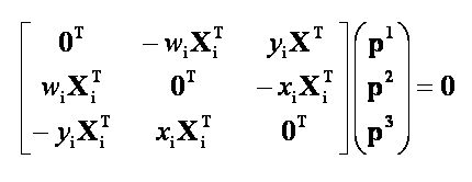
Where the piT are the rows of the matrix P. This leads to the equation systems:

Where the matrix on the left side is a 3x12 matrix and the vector on the right
side of the matrix contains all the 12 parameters of the camera.
Since two of the rows of the above linear equation system are linearly
dependent the matrix degenerates to a 2x12 matrix. Due to the fact that P can
be determined up to a scale by eleven elements, eleven equations and therefore
six (5.5) point correspondences are needed to get P.
2. Computation of the fundamental matrix
The fundamental F matrix is a 3x3 matrix of rank two that defines the geometry between the views of the two cameras. The elements of the matrix depend on the internal parameters and on the relative pose of the cameras. F satisfies the relation x'TFx = 0 where x' and x are corresponding points on the cameras' image planes. Each of the relations lead to one linear equation in the nine entries of F. Therefore given at least eight point correspondences, F can be determined up to scale. The resulting camera matrices and the fundamental matrix are then passed to Hauke Heibel whose current diploma thesis focuses on the realtime computation of depth maps from stereo images.
Visualisation on the 3D monitor
After the calculation of the depth map the depth map along with the
corresponding image has to be provided to the 4D Vision monitor to
generate a three dimensional view of the scene.
The generation of the three dimensional view is done by the tool "X3D Open-GL-Enhancer" from 4D vision which takes the image and the depth map and generates
eight displaced views of the scene. A filter on the monitor then provides each
eye of an observer with one of the eight views. Since each eye gets to see a
different sight of the scene a 3D effect arises.
Related links and literature
This section contains links to related literature, technical articles, descriptions of the hardware used and all other stuff that has some connection to the project.
1. Camera calibration
3D-Szenenrekonstruktion aus Bilddaten. Einführung in den Stand der Technik
Camera Calibration Toolbox for Matlab
Open Source Computer Vision Library
2. Visualisation on the 3D monitor
Homepage of the company that developed the monitor used in the project
| ProjectForm | |
|---|---|
| Title: | 3D view of stereo laparoscope in the operating room |
| Abstract: | In minimally invasive surgery, instruments and an endoscope camera are inserted into the patient's body through small ports or incisions, respectively. The goal here was to perform a calibration of a stereo endoscope and visualize their images on a 3D Monitor. |
| Student: | Benjamin Stetter |
| Director: | Nassir Navab |
| Supervisor: | Joerg Traub |
| Type: | SEP |
| Status: | finished |
| Start: | 2004/06/15 |
| Finish: | 2005/04/22 |