Virtual Engineering: Design of Optical See-through Displays
Abstract
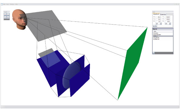
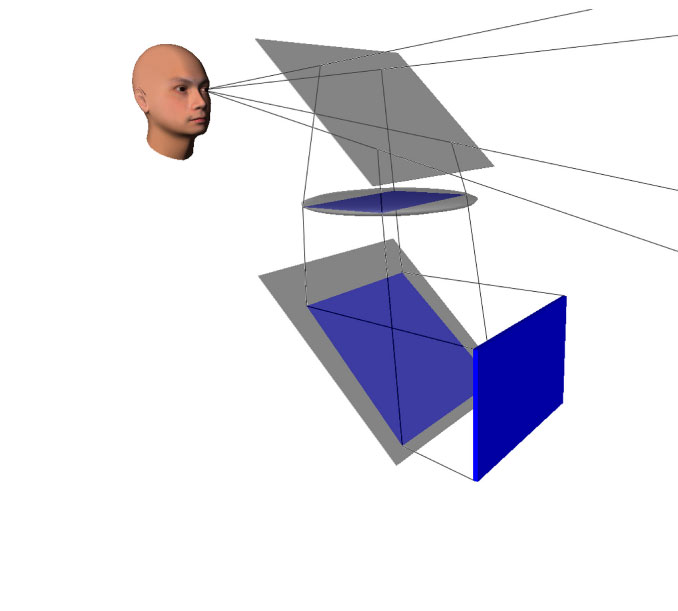
The design of optical see-through displays implicates special requirements to computer-aided optical design. Position and orientation of the focal plane as well as the image size and shape are of particular importance. This document introduces an approach for the design of a construction software for such optical systems and discusses some important aspects of a concrete implementation of particular optical elements (e.g. lenses, mirrors, etc.). A uniform structure for the optical elements was established that is able to represent all desired objects. An algorithm for the computation of the optical path and the image is described, that provides the sequential arrangement of the optical elements within the optical system. Based on this algorithm, an interactive construction tool is presented. The tool features an intuitive proceeding in finding new optical arrangements and to facilitate the understanding of the underlying effects and relationships. In extension, some aspects of the design of a conformal head-up display are discussed.Approach

Parts of the optical path are outside the geometry of some objects.
Aberration

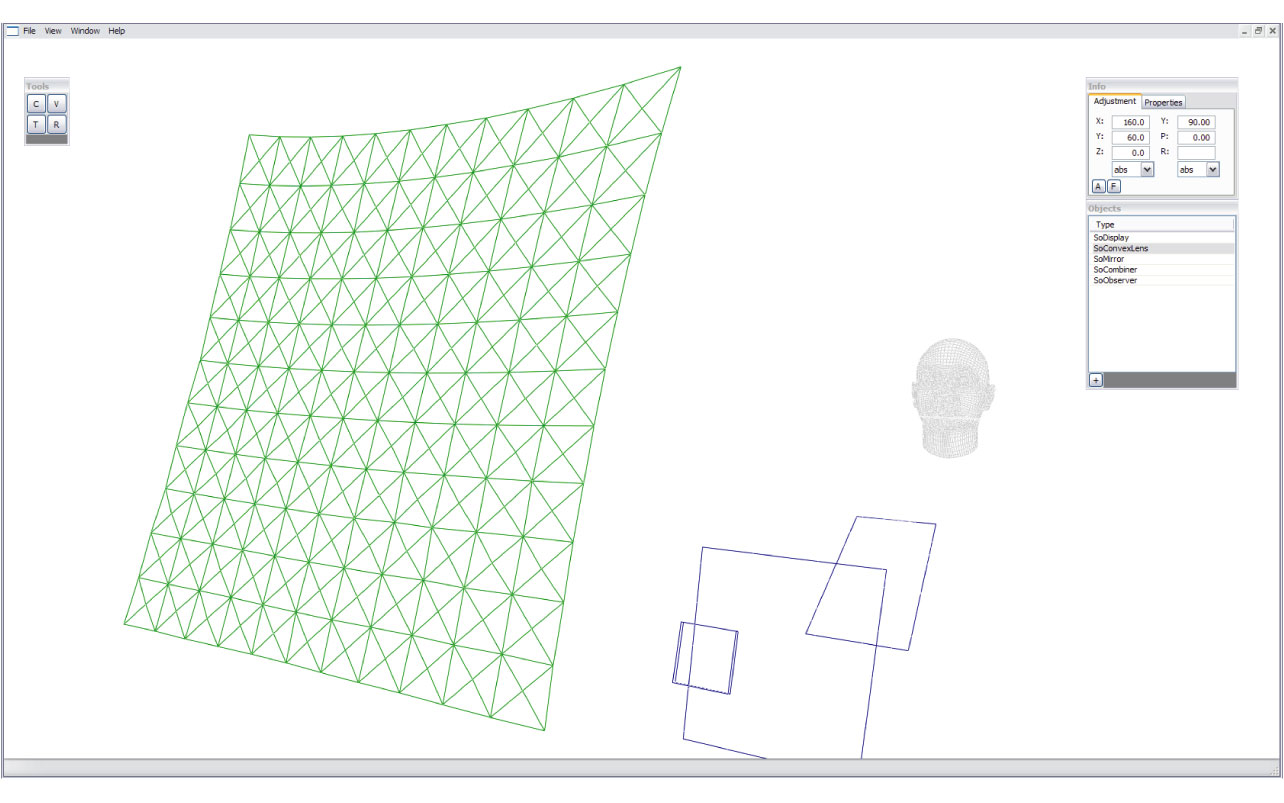
Representation of Distortion.
Implementation
The implementation of the construction tool is realized as an extension of the OpenGL? based Coin3D graphic library. This library is an implementation of the SGI Open Inventor specification. For the implementation of the GUI the wxWidgets library is used. wxWidgets is a cross-platform GUI toolkit that allows writing GUI applications on multiple platforms (e.g. Windows NT/2K/XP, Linux with X11, MacOS?).Deployment
- Please note that everything has to be compiled using the same C++ compiler and the same environment library.
- Sources: https://camplinux.in.tum.de/far_applications/OpticalDesignApp
- Install wxWidgets
- wxWidgets-2.8.7\build\msw\wx.dsw
- In VisStudio Build->Build Solution
- For completeness switch to release and build solution again
- Env-Var WXWIN point to wx folder where include folder is
- Open OpticalDesignApp.sln
- Build solution
- Have fun pushing play
Practice


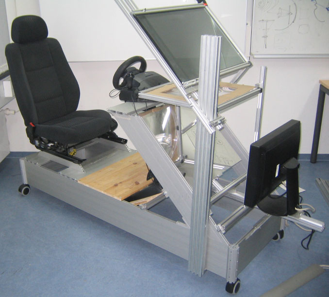
Virtual design and real prototype of a conformal, automotive HUD
Final Work
| Students.ProjectForm | |
|---|---|
| Title: | Virtual Engineering: Design of Optical See-through Displays |
| Abstract: | The design of optical see-through displays implicates special requirements to computer-aided optical design. Position and orientation of the focal plane as well as the image size and shape are of particular importance. This document introduces an approach for the design of a construction software for such optical systems and discusses some important aspects of a concrete implementation of particular optical elements (e.g. lenses, mirrors, etc.). A uniform structure for the optical elements was established that is able to represent all desired objects. An algorithm for the computation of the optical path and the image is described, that provides the sequential arrangement of the optical elements within the optical system. Based on this algorithm, an interactive construction tool is presented. The tool features an intuitive proceeding in finding new optical arrangements and to facilitate the understanding of the underlying effects and relationships. In extension, some aspects of the design of a conformal head-up display are discussed. |
| Student: | Stefan Machleidt |
| Director: | Gudrun Klinker |
| Supervisor: | Marcus Tönnis |
| Type: | SEP |
| Area: | |
| Status: | finished |
| Start: | 2008/05/01 |
| Finish: | 2008/11/12 |