-- MustafaKIsik - 20 Apr 2004
DelivARy User Manual

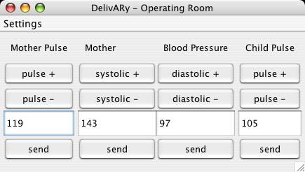
MedProc main application window

sending frequency configuration dialog

network configuration dialog
.
Keys for immediate program control:
Introduction
Welcome to DelivARy. The document at hand will provide you with some background to the DelivARy project/system and all necessary details to set up, start and operate the DelivARy-extended birth simulator. DelivARy extends a monitor and model based birth simulator, developed by the "Institute of Automatic Control Engineering" (Department of Electrical Engineering and Information Technology, TUM) and the "Clinic for Orthopedics" (Klinikum Rechts der Isar, Muenchen) to an augmented reality system. The purpose of the birth simulator is to assist teaching midwife students forceps deliveries. The conventional birth simulator is composed of- an anatomically correct plastic model of the female pelvis major with a vaginal access,
- a model baby head inside the pelvis
- and dedicated simulation, visualization and sensor control software.
Motivation
With the basic system the birth state and progress, especially the position and orientation of the model baby head within the female body model are only visible on a separate display as a 3D rendering. Forceps are neither tracked nor visualized at all, hence not viewable while inside the pelvis model. Due to this, visual feedback of interaction between model baby head and forceps is completely missing. The dedicated software's feature to show alphanumeric values of biomedical data is also only accessible via an external display. DelivARy extends the birth simulator's functionality by giving options to- superimpose 3D visualizations, such as virtual models of the baby head, hip bones and forceps at their respective real world coordinates
- and place visualizations of biomedical data within the view of an HMD-equipped trainee.
System Components
The hardware architecture of the existing system had to be expanded by integrating components such as a video see-through HMD and a tracking system for acquisition of real world object position & orientation data. Given the RAMP system, consisting of a video-see-through HMD with integrated inside-out tracking, as a critical resource, the suitability of the tracking system for delivering forceps pose data was also evaluated. Since the area tracked by the RAMP set-up proved to be very limited and tied to the field-of-view of the HMD-wearer, need arouse for a second tracking system. Immediate availability and the high precision of A.R.T. GmbH's outside-in dtrack system led to its adoption as tracking system of choice for the forceps. Due to the lack of source code access to the standard dedicated simulation, visualization and sensor control software a new program for providing and controlling biomedical data was developed. The program is java-based and provides data via TCP network communication.Setting Up and Running the System
The following software components need to be activated in order to run the birth simulator with AR extensions:- RAMP Server - realizes HMD-tracking
- ART dtrack Server - tracks and provides forceps pose
- RAMP Client - processes all tracking data and displays perspective correct visualizations within HMD
- MedProc - provides biomedical data for RAMP client
- IP, remote and local port addresses of the ART tracking server
- listening port for MedProc data reception
- model files for forceps, female anatomy, skin and baby head
- folder containing monitor models for visualization of biomedical data
- IP and port address of the data recipient (RAMP Client) are both changeable via "Settings/Network Configuration"
- The data sending frequency is adjustable in "Settings/Continuous Sending Frequency"

MedProc main application window

sending frequency configuration dialog

network configuration dialog
Program control
The RAMP-Client offers a variety of features which are accessible via hotkey-combinations, once the DelivARy-Visualization is activated by pressing the keys <9> followed by- <F> turn monitor for biomedical data visualization on/off
- <A> switch monitor to show mother pulse
- <S> switch monitor to show baby pulse
- <D> switch monitor to show mother blood pressure
- <X> switch between 3D baby head and sphere visualization
- <Z> cycle through additional models availiable for visualization: bone structure, skin, skin and bone structure, nothing
- <C> choose object to be calibrated
- <G>, <H> and <J> increase x,y and z translation
- <V>, <N> and <M> decrease x,y and z translation
- <I>, <O> and <P> increase x,y and z axis rotation
- <K>, <L> and <U> decrease x,y and z axis rotation
- <F5>, <F6> and <F7> increase/decrease the x, y and z translation
- <F9>, <F10> and <F11> increase/decrease the x, y and z axis rotation
- <F8> negate the translation/rotation direction
- <F12> save the calibration
| I | Attachment  | Action | Size | Date | Who | Comment |
|---|---|---|---|---|---|---|
| | MedProcFrequency.jpg | manage | 6.8 K | 20 Apr 2004 - 14:50 | MustafaKIsik | |
| | MedProcMain.jpg | manage | 22.1 K | 20 Apr 2004 - 14:51 | MustafaKIsik | |
| | MedProcNetwork.jpg | manage | 8.0 K | 20 Apr 2004 - 14:51 | MustafaKIsik |